
Flow Equalization Tank Articles & Analysis
13 articles found
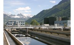
Capacity and redundancy. Plants are sized for peak flows and future growth. Under sizing can cause frequent bypasses or overflows, while extreme overdesign wastes capital. ...

The system was engineered with state of the art PEWE Command Control panel. Custom equalization/pH tank, pumps and PolyAccu Dose chemical feed subsystems completed the package treatment plant. Controlled Operation The wastewater first enters the OZ oil/water separator where free oils readily are collected at the surface without the aid of chemistry. Next the ...
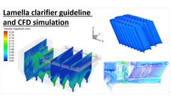
Other parts of a lamella clarifier tank are the water inlet, sludge settling and water outlet zone. The most important design guideline is to achieve an equal flow inside the lamella clarifier tank and to reduce turbulences so that the maximum number of solids can be settled down in the lamella clarifier modules. ...

The first compartment is an covered anaerobic tank that removes floatable and settleable solids. The second chamber is a combination anoxic basin/flow equalization basin to buffer peak flows and loads as well as provide an anoxic step for denitrification if required. ...
It consists of a four-chambered rectangular tank. Since commissioning in July of 2012 this plant has performed well. ...

Background, the project’s three flow equalization, recirculation, and FAST system dosing tanks. The system was designed for simplicity of operation and service. ...

Class I, Division 1 refers to the following hazardous locations in the facility: • Sanitary Sewer/Combined Sewer (Inside) • Wastewater Pumping Station Wet Wells (Entire room) • Above-grade Wastewater Pumping Station (Entire space) • Maintenance Holes (Inside) • Junction Chambers (Inside) • Inverted Siphons • Catch Basins Class I, Division 2 refers to the ...

The treatment process comprises of the following stages: Coarse screening & Lift Pump Station Pre-treatment Combined Units Flow Equalization and Aeration Tanks Primary Clarification Pre-Treatment Stage Secondary Biological Treatment Fine Screening and Tertiary Treatment, using MBR Technology Sludge Dewatering using Containerized ...

Because most of the MBRs were designed according to standardized guidance, system configuration of the plants was similar; pre-denitrification using the Modified Ludzack-Ettinger (MLE) process with membrane units submerged in aerobic tanks, following a fine screen and flow equalization tank. This led to effluent quality with ...
F/M ratio is a measure of food provided to bacteria under aeration in a tank. “Food provided” refers to the biochemical oxygen demand (BOD) entering the aeration tank per day, measured in pounds. ...

Two banks of model 300/600 LSGM's were chosen for this application due to varying flows throughout the day. Based upon the level of influent into the LSGM Heads, the second set of heads were provided to initiate when flow is at high/high, based upon level sensors in the equalization tank. When flow is low, the ...
Its major components are: 5,000-gallon one-compartment grease tank. Most tanks are concrete and made by Jensen Precast from Fontana, Calif. 5,000-gallon one-compartment septic tank. Existing 5,000-gallon dosing tank retrofitted with two 3.0 FAST aerobic treatment units from Bio-Microbics Inc., Shawnee, Kan. 6,000-gallon ...

Two floors below those are a series of tanks, pumps, and piping. The first step is the pumping of the effluent into a headbox, from which it then flows into a primary clarifier; any remaining flow returns to the flow equalization for recovery and reuse of the system. ...