
Vapor Extraction Well Articles & Analysis
22 articles found

Approach: For the thermal design, every heater boring was equipped with a co-located soil vapor extraction well, allowing for the best pneumatic connection to the bedrock fracture system. The concentration of TCE in these vapor streams from individual wells was used to gauge remedial completeness. ...
Approach: TCH heaters were installed to depths between 23 and 30 ft bgs to heat the target treatment zone (TTZ) to ...

OBJECTIVE The design involved 5 VertebraeTM well systems to provide targeted air sparging (AS) utilizing 29 independent well segments and 5 VertebraeTM well systems to provide soil vapor extraction (SVE) utilizing 19 independent well segments. The individual well systems varied ...

As part of a Corrective Action Plan (CAP) submitted to NYSDEC, a consultant selected Horizontal Soil Vapor Extraction Wells (HSVE) to expand an on-site vapor extraction system in New York. Directional Technologies worked with the consultant on the horizontal well screen design and ...

In 2008, the EPA obligated approximately $5.2 million for cleanup activities at the site. Since then, 21 groundwater extraction wells, 10 monitoring wells, 4 injection wells and 62 soil vapor extraction (SVE) wells have been installed, and a treatment plant was built to house a ...
In this approach, the soil and aquifer are heated by electrical resistance to current from underground electrodes and by injection of superheated steam into the wells. High temperatures increase the mobility of viscous NAPLs; some components actually boil and can be removed as vapor. Dual phase extraction wells recover soil ...

On this State Funded Clean-Up project, Global was the project engineer and was responsible for the design of an air sparging/soil vapor extraction remediation system. The system included five soil vapor extraction wells and twelve sparging wells that operated on a rotating schedule. One of the ...

The two intervals were designed to heat the DNAPL in the middle fine grain unit and the lower clay unit. Vapor extraction wells were screened at 5 feet bgs. There was also a network of horizontal vapor extraction wells installed at the surface underneath a plenum. ...

Phase I treated a two-acre area using 26 steam injection points, 26 soil vapor extraction points, and 12 product recovery wells. The maximum recovery rate peaked at 350 gallons of product per day with over 36,500 gallons of total diesel product recovered throughout the phase. ...
A soil vapor extraction (SVE) system was installed in the summer and fall of 1995. The SVE system consisted of sixteen-vapor extraction wells installed at depths ranging from nine to 19 feet bgs. ...

The remediation goal was driven by vapor intrusion risk requiring final levels to be below commercial soil gas screening criteria. GEO’s patented GTR© system was used for In-Situ Thermal Remediation (ISTR) to significantly accelerate PCE mass removal by heating affected soils and/or groundwater to target temperatures of 100°C. C3 Technology refrigerated ...
The resistance of the electricity traveling through the ground creates heat that will vaporize volatile organic compounds. These vapors are collected and treated through a vapor extraction recovery system. ...
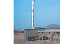
To aggressively remove the subsurface contaminants, the engineers blanketed the old airport tarmac with 2,000 soil vapor extraction (SVE) wells and 1,000 sparge wells. The massive airflow was directed from the wells to a single treatment system. ...
Directional Technologies Is The Expert At Horizontal Soil Vapor Extraction A horizontal soil vapor extraction well and two horizontal air sparge wells rapidly remediate contamination in situ under a research and development facility. These horizontal wells were installed by ...
Business at the gas station would slow down or stop for an extended period of time if a vertical air sparge and soil vapor extraction wells had to be drilled through the rock, because the wells would surround the pump island, block the driveways, and even interfere with access to the store itself. ...

The vapors from both the vacuum extraction as well as the groundwater air stripping system from the source will be treated using a thermal oxidation system. The vapors from the SVE wells in the surrounding lowconcentration VOC areas will be treated using GAC. ...
Raw materials for CFC/HCFC production included hydrofluoric acid, carbon tetrachloride, chloroform, 1,1,1- trichloroethane (1,1,1-TCA), and antimony pentachloride catalyst. Pilot testing of the soil vapor extraction (SVE) remediation system was initiated in October 2000. ...
The remedy implemented at the site consists of a site-wide groundwater recovery and treatment system combined with a source area soil vapor extraction system. The soil vapor extraction system consists of 62 wells that were installed in 2009. ...
Project Description An active industrial facility in South Central Los Angeles was impacted by tetrachloroethylene (PCE) and trichloroethylene (TCE; former staging area degreasing) operations as a part of its operations. A phased approach to soil vapor extraction (SVE) remediation was employed: the goal of Phase I was to attain high contaminant mass removal rates ...
Static water levels generally equilibrate at depths of 5 and 7 feetbgs, and vary seasonally by a few feet. Vapor Treatment System Design 100 SCFM system Sixteen vapor extraction wells were operated in cycles Maximum initial concentration achieved was 8,068ppmV Performance and Results Using a G.E.O. refrigerated ...